A scrambler breaks up repetitive patterns in transmitted data. But how can a receiver tell when a bit changes during transmission? A CRC (Cyclic Redundancy Check) adds a short check value to the data so the receiver can detect corruption.
This article follows a small CRC-3 example through the entire calculation. In the interactive lab, you can change the data and generator polynomial and inject errors into received bits. Finally, we show how FPGA shift registers and XOR gates implement the same calculation.
Learn with the video: EasyFPGA CRC lesson on YouTube (in Korean)
Watch the explanation, then explore CRC calculation and error detection in the lab below.
Why CRC Is Needed Even When Errors Are Rare
On a high-speed link, noise, jitter, crosstalk, and reflections can cause a receiver to misinterpret a bit. Good link design can make errors very unlikely, but the receiver still needs a way to check whether a frame was corrupted.
FPGA IBERT is a diagnostic tool that sends known test patterns through high-speed transceivers and compares received patterns to observe bit errors. Zero errors over two hours means no errors were observed during that test under those conditions. It does not guarantee error-free operation under every future condition.
CRC does not prevent errors. It provides a check value for detecting data corruption that has occurred. The protocol decides whether to discard a damaged frame or request retransmission.
| Function | Transmitter | Receiver |
|---|---|---|
| Scrambler | Transform data patterns | Recover the original data by descrambling |
| CRC | Calculate and append a check value | Use the check value to detect corruption |
Scramblers and CRC circuits can both use XOR gates and shift registers, but they serve different purposes. A CRC field is appended to the protected data; it does not replace that data.
What Does a CRC Calculate?
We will use an educational CRC model with these settings:
| Item | Value |
|---|---|
| Message | 1101 |
| Generator polynomial | G(x) = x³ + x + 1 → 1011 |
| CRC width | 3 bits, the degree of the generator polynomial |
| Processing order | Leftmost, most significant bit first |
| Initial state / final XOR | 000 / none |
| Calculation | Append three zeros to the message before division |
From left to right, the bits of 1011 are the coefficients of x³, x², x, and the constant term. The coefficient of x² is zero, so G(x) = x³ + x + 1. The generator is written with four bits, but the CRC field contains three bits.
CRC division is not ordinary integer division. It is polynomial division over GF(2), with coefficients of zero or one. XOR replaces subtraction, with no carries or borrows.
| |
The transmitter appends as many zeros as the CRC width, producing 1101000. It repeatedly aligns 1011 with the leftmost remaining one and applies XOR.
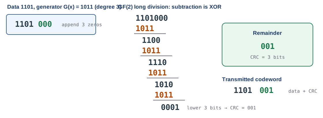
Here is the calculation using the full bit string. Leading zeros are retained to show alignment.
| Step | Current value | Aligned generator | XOR result |
|---|---|---|---|
| 1 | 1101000 | 1011000 | 0110000 |
| 2 | 0110000 | 0101100 | 0011100 |
| 3 | 0011100 | 0010110 | 0001010 |
| 4 | 0001010 | 0001011 | 0000001 |
The remaining polynomial now has degree less than three, so division stops. The last three bits, 001, are the CRC.
| |
Keep these values separate. 1101000 is processed by the transmitter to calculate the CRC. 1101001 is the complete codeword checked by the receiver.
Calculate a CRC and Flip Some Bits
The lab below adapts the lesson’s CRC exercise for the blog. It uses the simplified polynomial-division model above, rather than a standard CRC-32 calculation: zero initial state, MSB first, no reflection or final XOR, and appended zeros for transmitter calculation.
Try these steps:
- With the defaults
1101and1011, click Next XOR until the final remainder is001. - Click the second bit of the received frame
1101001. It becomes1001001, and the syndrome becomes111. - Click Clear errors to return the syndrome to
000. - With the default example, click Undetected error example. Even though three bits change, the syndrome is
000.
For actual standard parameters such as Init, RefIn, RefOut, and XorOut, use the existing CRC Calculator and compare the result with the standard’s test vectors.
The Receiver Checks the Syndrome
The receiver divides the entire codeword, including both the message and CRC, by the same generator polynomial. It does not append more zeros for this check.
| Received codeword | Meaning | Remainder (syndrome) |
|---|---|---|
1101001 | Unchanged example | 000 |
1001001 | Second bit flipped | 111 |
1100001 | Fourth bit flipped | 011 |
The syndrome is the remainder obtained by the check. In this educational model, a nonzero syndrome means an error was detected. A zero syndrome means “no error was detected.”
Why does zero not prove that there was no error? If the error pattern itself is divisible by the generator, the receiver cannot distinguish it from a valid codeword.
| |
Both the original codeword and the error pattern are divisible by 1011. Their XOR is also divisible, so this error is undetected. Understanding CRC requires recognizing both detected and undetected errors.
How Long Division Becomes an LFSR Circuit
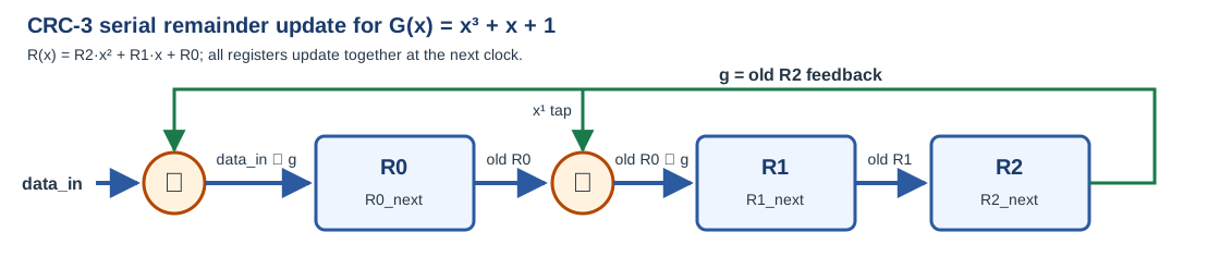
We do not need to store the entire bit string at every step. A three-bit register can hold the current remainder and update it whenever the next input bit arrives.
| |
Multiplication by x corresponds to shifting left by one bit. If appending the next bit produces an x³ term, XOR with G(x) removes it. Since G(x) = x³ + x + 1, x³ is replaced by x + 1 in the remainder calculation.
For current state R2 R1 R0, the update equations are below. Every value on the right is from before the update.
| |
| |
Nonblocking assignments (<=) make all three registers read the same previous state and update together at the clock edge. To calculate the transmitter CRC, feed in 1101000 from left to right.
| Input step | Input bit | State after processing |
|---|---|---|
| Initial state | — | 000 |
| 1 | 1 | 001 |
| 2 | 1 | 011 |
| 3 | 0 | 110 |
| 4 | 1 | 110 |
| 5 | 0 | 111 |
| 6 | 0 | 101 |
| 7 | 0 | 001 |
The final state 001 matches the long-division remainder. You can follow the same sequence under Register states in the lab.

For receiver checking, reset the state to 000 and feed in 1101001. The final state is 000. A CRC checker checks a remainder; it is not a decoder that restores the data.
This example is a one-bit serial circuit for learning. Actual high-speed links may need a parallel CRC that processes multiple bits per clock, along with separate control for frame boundaries and CRC-field transmission order.
Which Errors Can a CRC Detect?
Detection guarantees depend on the generator polynomial and the protected length. Common degree-r generators have both a leading coefficient and a constant coefficient of one.
| Error type | Guarantee condition |
|---|---|
| Single-bit flip | A generator with at least two nonzero terms detects all single-bit errors |
| Burst error of length r or less | A degree-r CRC with constant coefficient one detects all such bursts |
| Odd number of bit flips | All are detected if the generator has (x + 1) as a factor |
| Bit flips at multiple positions | Check the minimum Hamming distance for the polynomial and protected length |
Burst length is the span from the first erroneous bit to the last, rather than the number of flipped bits. Bits inside that span need not all change. The undetected pattern 1011 above flips three bits but has burst length four, so it does not contradict CRC-3’s guarantee of detecting bursts of length three or less.
Hamming distance is the number of differing bits between two valid codewords. If the minimum distance between valid codewords is d, all patterns of up to d−1 bit flips are detected. Longer protected blocks allow more combinations of error positions and can reduce the minimum distance. Detection guarantees therefore need not be the same for 1,000-byte and 11,000-byte blocks. See Philip Koopman’s CRC polynomial analysis for performance as a function of length.
Connecting the Example to Ethernet FCS
Ethernet appends a four-byte FCS (Frame Check Sequence) to a frame. A typical untagged frame can be illustrated as follows:
| |
The FCS covers MAC frame fields from the Destination Address through the end of Data/Pad. Preamble and SFD are excluded. If a VLAN tag is present, that frame field is included too. See Intel’s Ethernet MAC description of FCS calculation for the covered fields.
The educational CRC-3 and actual Ethernet CRC-32 use different calculation settings. Initial state, bit-processing order, RefIn/RefOut, final XOR, and protected fields must all match. Actual CRC implementations may check the entire received frame against a specified residue, so do not generalize that every CRC receiver must obtain zero.
Parameters and the reference check value for CRC-32/ISO-HDLC are listed in the CRC RevEng catalogue. When implementing a standard, verify the complete configuration against its specification and test vectors rather than relying on its name alone.
What Happens After a CRC Error?
CRC generally neither identifies error locations nor corrects damaged bits. A receiver may discard a frame after detecting corruption or, if the protocol supports it, request retransmission using ARQ (Automatic Repeat reQuest). Error correction requires a separate technique such as ECC/FEC.
The key values in this example are the transmitter calculation input 1101000, CRC 001, transmitted codeword 1101001, and unchanged receiver syndrome 000. Keeping them separate connects polynomial division to the identical computation in an LFSR circuit. The next SERDES topic examines how this data is sent as a serial signal and recovered as parallel data.
© 2026 EasyFPGA. All rights reserved.
The EasyFPGA-created explanations, illustrations, code, and interactive tools in this article may be viewed and run on this website for personal learning. Except as permitted by law, copying, modification, redistribution, or incorporation into other products or services requires prior written permission from EasyFPGA. Public access does not grant an open-source license. Request permission through the contact page. Rights to external reference materials remain with their respective owners.